The latest Installs, patches and release notes
Customer HubSearch our knowledge base, or open technical queries
Explore engineering trends, case studies, tricks, and tips
EventsTechnical seminars and webinars by bridge experts
Bridge Insight : New Development in Long Span Arch Bridges
All features designed to fit to your projects
Unlimited Nodes and Elements
Plus Advance Full1D Elements
(Truss, General Beam, Tapered Beam, Compression Only,Tension Only, Gap, Hook, Cable-Equivalent Truss Type)
1D Elements (Cable-Elastic Catenary Type)
Plus Advance Full2D Elements
(Plane Stress, Plane Strain, Plate-Thick/Thin, Axisymmetric)
3D Elements
(Tetrahedron Solid, Pentahedron Solid, Hexahedron Solid)
Point Spring (Linear/Nonlinear)
Plus Advance FullGeneral Spring
Plus Advance FullElastic Link(General/Rigid/Tension/Comp.)
Plus Advance FullGeneral Link(Element Type/Force Type)
Plus Advance FullRigid Link
Plus Advance FullBeam End Release
Plus Advance FullBeam End Offset
Plus Advance FullPlate End Release
Plus Advance FullNode Local Axis
Plus Advance FullEffective Width Scale Factor
Plus Advance FullSection Stiffness Scale Factor
Plus Advance FullMaterial
(Steel, Concrete, SRC, and User)
Time Dependent Material
Plus Advance FullDB, User, Value Sections
Plus Advance FullSRC Sections
Plus Advance FullCombined Sections
Plus Advance FullPSC Sections
Plus Advance FullTapered Sections
Plus Advance FullComposite Sections (PSC/Steel/User Section)
Plus Advance FullSectional Property Calculator (User Section)
Plus Advance FullThickness-Value
Plus Advance FullThickness-Stiffened
Plus Advance FullBeam / Column / Plate / Shell
Plus Advance FullCulverts(Slab and Box)
Plus Advance FullRC Slab Bridge
Plus Advance FullRC Frame Bridge
Plus Advance FullGrillage Model
Plus Advance FullTransverse Analysis Model
Plus Advance FullSteel Composite Bridge This is an additional paid option
Plus Advance FullPrestressed Composite Bridge This is an additional paid option
Plus Advance FullFree Cantilever Method Bridge
Plus Advance FullIncrementally Launched Method Bridge
Plus Advance FullMovable Scaffolding System
Plus Advance FullFull Staging Method
Plus Advance FullCable Stayed Bridge
Plus Advance FullSuspension Bridge
Plus Advance FullStatic Analysis
Plus Advance Full
Pushover Analysis
(Auto Plastic Hinge Definition, Auto PM Interaction curve for hinge formation, Obtain Performance point as per FEMA)
Boundary Nonlinear Dynamic Analysis
using Gap, Hook, Damper, Isolator, and Hysteretic System
Inelastic Time History Analysis
This is an additional paid option
(Beam Elements, Lumped Hinges & Distributed Hinges, Automatic Calculation of Yield Strength, Axial load – biaxial moment interaction, Fiber Model Analysis)
Construction Stage Analysis
Construction Stage Analysis is available up to 10 stages for Plus version
(Creep/Shrinkage and Modulus of Elasticity, Tendon losses in tendons)
Heat of Hydration Analysis for Mass Concrete
This is an additional paid option
(Creep/Shrinkage and Modulus of Elasticity, Tendon losses in tendons)
Buckling Analysis
Plus Advance FullThermal Stress Analysis
Plus Advance FullLarge Displacement(Forward/Backward) Analysis
(Cable-Stayed Bridges, Cable Tuning, Suspension Bridges)
Rail Track Analysis
This is an additional paid option
- Auto-generation wizard of rail track analysis model
- Rail track-structure interaction
- Temperature, acceleration and braking loads
Bridge Load Rating
Plus Advance Full
GSD(General Section Design)
This is an additional paid option
- Draw Arbitrary Cross-sections(RC, Steel, Composite)
- Capacity Curves(P-M, M-M, 3D) & Capacity Check Ratio
- Moment-Curvature Curves for Different Axial Loads
- Stress Contours for Combined Loading
FX+ Modeler
This is an additional paid option
- Finite Element Modeler & Auto-Mesh Generator
- Export model to Civil
UK Bridge Assessment
This is an additional paid option
- PC Composite Assessment as per CS454
- Special Vehicle(All Model 2) as per CS 454
The number of points to define the section in I-end and J-end of the taper section to be generated has to be the same.
Since a Composite T (say end I of taper section) will have lesser defining points ( O ) as compared to Composite I section (end J ), the tapered element could not be generated. However an as an alternative, we could define T section with so many points as that of I section and generate the tapering.
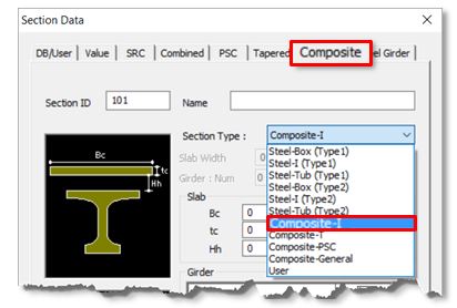
Under [Properties > Section Properties, click Add > Composite tab > Composite I] option from the drop-down menu, enter the data as per the guide diagram shown below and generate the required I section.
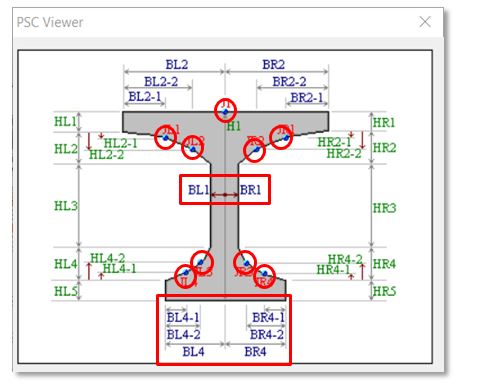
To generate a composite T section, using the composite I girder option, enter the BL1 and BR1 values slightly lesser (say, 0.5mm lesser) than the BL4 and BR4 values. By doing so, the additional points required would have been entered, still retaining the sectional properties of a T section. By this way, the tapering of the section could be accomplished. Once the two sections are generated, the tapered section can now be made using these two section properties.
To generate such a tapered section, follow the steps below in sequence: Click on [Properties > Section Properties > Add]
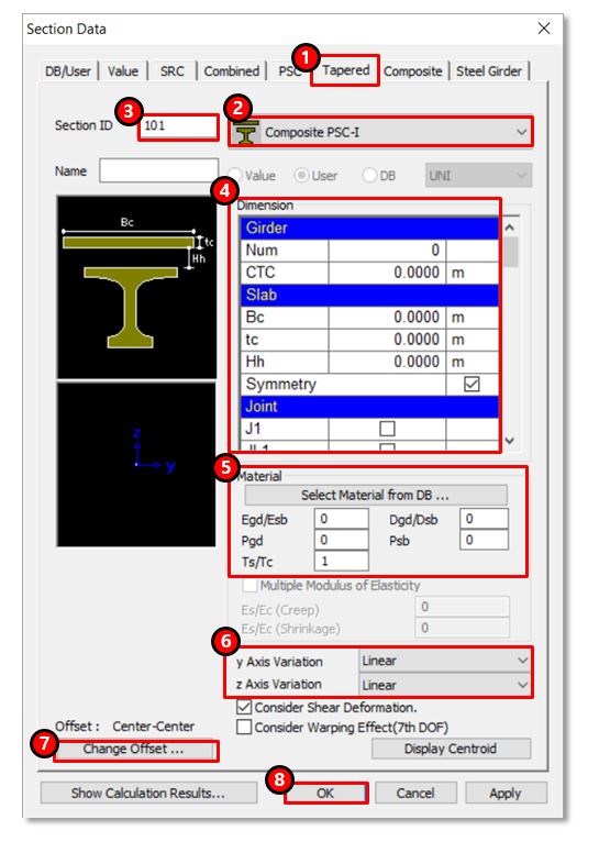
1. Click on Tapered
2. Select Composite PSC-I
3. Enter Name
4. Enter basic data like slab width, thickness, etc, and import the “Size-I” and “Size-J” sections.
These would be the sections that are generated using the Composite I girder option.
5. Enter material data for equivalent section property calculations
6. Select the type of variation (Linear, Parabolic, or Cubic)
7. Modify the offset as required
8. Click OK
From Main Menu select [View > Display Option]
1. Thickness of the plate element
2.To distinguish plate elements from beam elements
3. To show the outline of the Inactive elements
4. Display only to certain parts
If you enable the Display by Group option in the Display, only the information of the selected group is displayed. In the figure below on left, the entire " live load surcharge" is displayed, while in the figure further below only a part of the upper slab loads as defined in a group is displayed. Display by Group options can be applied to loads as well as all display information that can be expressed in midas Civil.
5. Different colored elements depending on the thickness
The difference between lane element and cross beam element for vehicular load distribution is in considering the transverse rigidity of the system and the kind of model generated (line, plate, or grillage model). In case, the structure is modeled as a line element and is assigned whole transverse cross-sectional property, lane element for vehicular load distribution option is used. For grillage models, live load distribution occurs as per the rigidity of transverse members (slab/diaphragm), hence the cross beam method for vehicular load distribution is used.
In the cross beam method, a cross-beam structure group (transverse elements group) has to be defined and selected for transverse distribution of vehicular load as shown.
These types of warnings during analysis can be avoided by altering the default convergence criteria from Main Control Data as shown below. From Main Menu select [Analysis > Main Control Data]
The number of iterations for load case convergence can be increased or convergence tolerance can be altered if load cases do not converge.