


In this content, we will discuss the process of calculating the shear strength of a reinforced concrete member.
Key topics include
- The common theoretical background of the strength design method, ACI 318-19, and limit state design method, Eurocode2
- The process of calculating shear strength based on the angle of inclination(crack angle)
1. Shear Cracking in Concrete Members
First, let's review the mechanism and model of shear cracking.
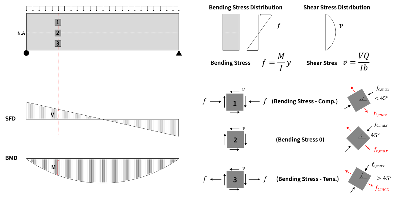
In a member subjected to bending, a bending moment (M) and a shear force (V) act simultaneously, as shown in the figure above.
This is a basic engineering principle, and the bending stress (F) and shear stress (V) for each layer can be calculated as shown in the equation above.
Using the transformation formula for plane stress, the direction and magnitude of the principal stress can be calculated, and the direction of the maximum principal tensile stress for each position can be calculated.
At the neutral axis position “2”, the bending stress is zero and only the shear stress is acting.
Therefore, the direction of the principal stress is 45 degrees, and for the "3" position, where bending tensile stress occurs, the maximum compressive principal stress will be at an angle less than 45 degrees.
At the end of the member, the shear stress is zero and the direction of the bending tensile stress is the same as the direction of the maximum tensile principal stress.
Based on this, we can say that the angle and direction of the crack will have the following geometry.
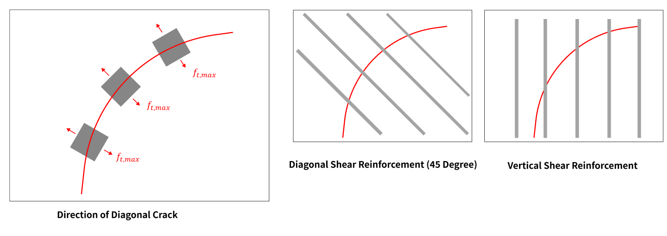
Reinforcing bars are placed at the bottom of the member to resist the bending tensile stress, and reinforcing bars placed along the direction of the crack to resist the crack are called shear reinforcement bars or stirrups.
Shear reinforcement is usually placed at 90 degrees for ease of construction. The direction of the crack and the angle of the shear reinforcement can be seen in the diagram above.
2. Shear Truss Model
For analyzing beam members subjected to bending moments and shear forces, two main concepts can be used: the "truss model" and the "arch model".
Since all major design guidelines consider the truss model, so we will only discuss the truss model.
For a truss model, the stress flow within the beam can be modeled as a truss as follows.
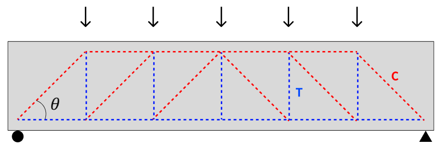
Compression and tension members in the truss model
As shown in the figure above, the upper chord member and the diagonal member (concrete member) resist the compressive force, while the lower chord member (flexure reinforcement) and the vertical member (shear reinforcement) resist the tensile force.
The crack angle (θ) in a truss model is the angle between the inclined member (concrete strut) and the lower chord member.
And the truss model used in ACI and Eurocode is as follows.
- ACI: 45-degree Truss Model with a fixed 45-degree angle
- Eurocode: variable angle truss model (angle is not fixed)
Let's look at the force equilibrium as a function of crack angle (θ) and angle of shear reinforcement (α).
Crack surface and shear reinforcement arrangement according to crack angle and angle of shear reinforcement
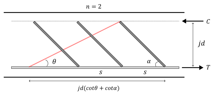
When the crack progresses according to the crack angle, the force equilibrium according to the crack angle (θ) and the reinforcement angle (α) can be expressed as shown below.
- Number of shear bars resisting the crack: n
- Spacing of shear bars: s
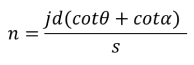
The average stress (v_scm) at the crack plane indicated by the red dotted line above can be calculated as below.
If we assume that the number of shear bars placed on the crack surface is 1, and then calculate the average stress at the crack surface, we can get the same average stress value as above.
In other words, you can calculate the force equilibrium for a truss model with one shear bar, and the result shows that the shear force and the tensile force generated by the shear bar are in force equilibrium.
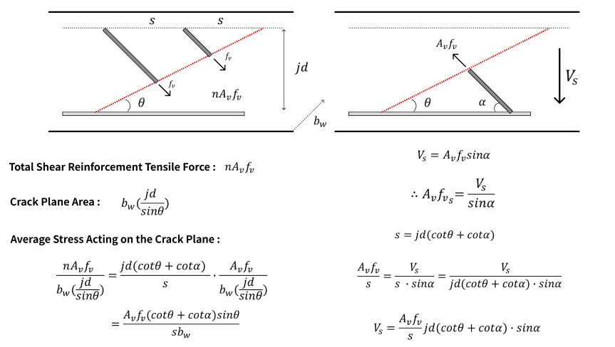
The tensile force on a single shear reinforcement can be expressed by the formula.
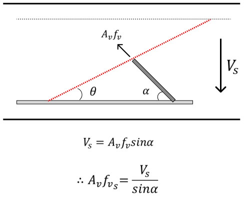
Relationship between tensile and shear forces on a single reinforcement
The relationship between the spacing of a single reinforcement (n = 1) and the arm length is as follows:
![]()
The tensile force per unit length can be calculated by dividing the tensile force applied to the shear reinforcement by the spacing (s).
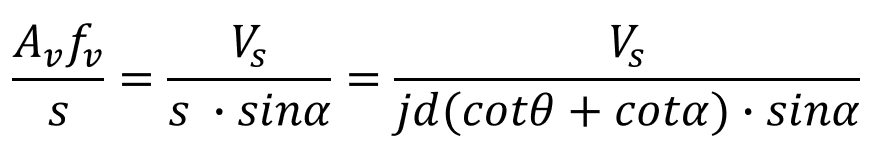
The shear resistance of shear reinforcement can be expressed by the following formula.
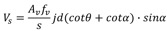 Shear resistance due to shear reinforcement
In Eurocode 2 and ACI 318-19, the "design shear strength of members with vertical stirrups" and "design shear strength of members with inclined shear bars" can be calculated using the above general equations.
The equations in Eurocode 2 calculate the crack inclination angle (θ) as a variable, whereas ACI 318-19 assumes a crack inclination angle of 45 degrees.

It can be observed that the ACI and Eurocode equations for "Calculation of shear strength of shear reinforcement" are derived from the same equation.
However, the difference is,
- In ACI, the shear strength in RC is calculated by combining the shear strength of the shear reinforcement and the shear strength of the concrete.
- In Eurocode, the shear strength is calculated from the shear strength of the reinforcement alone. In addition, the angle of inclination of the stirrups is taken into account.
3. Design shear strength
In Eurocode, the yielding behavior is limited in order to prevent brittle failure.
1) Shear reinforcement is designed to yield first
→ Compressive failure of the concrete strut shall not occur before the yielding of the shear reinforcement.
The first condition is shown in the equation below.
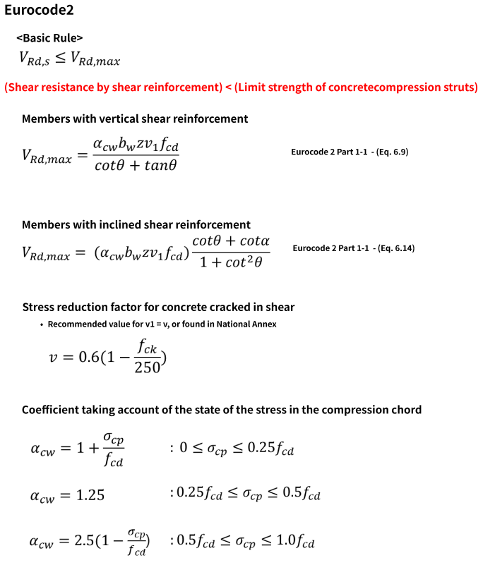
It is important to note that the design shear strength Vd is not determined as the smaller of the two values below.
"Shear strength due to shear reinforcement"
"Shear strength due to concrete"
If Vsd (shear strength due to shear reinforcement) is greater than Vdmax (shear strength due to concrete), it is not an appropriate design because the compressive failure of the concrete will occur first.
As shown in the figure below, as θ increases, the shear strength due to shear reinforcement yielding (V_sd) becomes smaller and the shear strength due to concrete compressive failure (V_d,max) becomes larger.

You can check more of these details in the download file.