Get Started midas Civil
 Featured blog of this week


1. Introduction
When performing the Rail-Structure Interaction (RSI), It is often found that the stress limits are exceeding the permissible values. So there are some countermeasures to ensure safety. Let’s look at how we can implement these control measures which affect the stresses in rails when performing rail structure interaction.
RSI refers to the interaction between railway tracks and concrete bridge structures. Considering two cases here. One involves the interaction between rail and ground, while the other shows the interaction between the rail and the bridge structure. The second case is the area of interest, as it involves the interaction of the rail with the bridge.
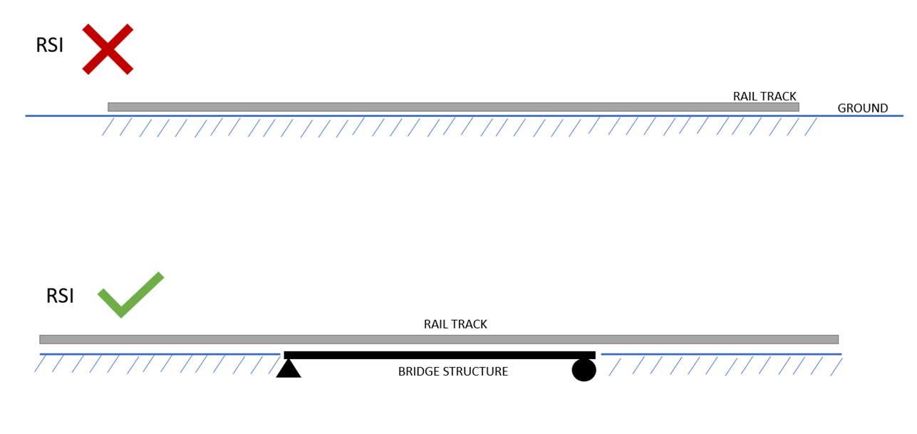
Figure 1.1 Schematic Diagram for RSI
With the development of high-speed trains globally, continuous welded rail (CWR) is used for railroad construction. CWR provides some advantages over conventional fastener joints in terms of maintenance and riding comfort but at the same time possess a new challenge for the rail-bridge interaction problem. Now, let's discuss the various challenges that affect RSI.
1.1 Temperature
To understand the effect of temperature, let’s take a scenario and study the stresses in railway tracks when there is no bridge and we increase the temperature. The ground itself will remain unaffected by the temperature change, but the railway track will tend to expand. Within this scenario, we can examine two distinct zones: the central zone and the expansion zone.
a. Central Zone:
With a change in temperature, the central portion of CWR is not subjected to any longitudinal displacement and will be subjected to temperature stress, and the stress profile is constant here.
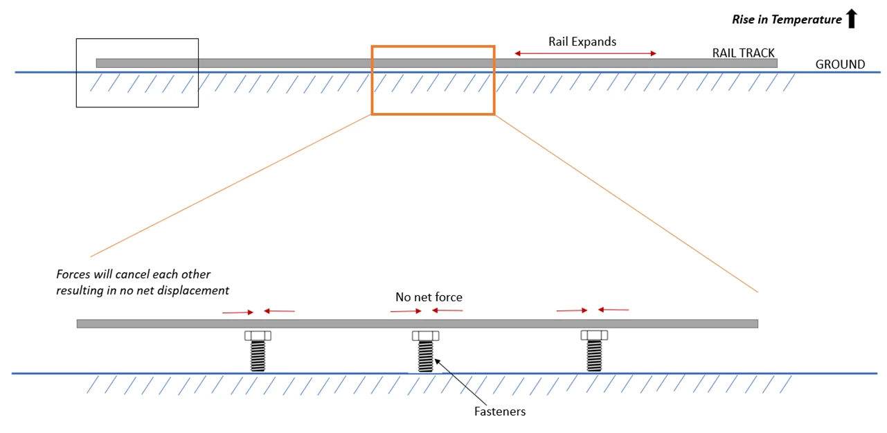
Figure 1.2 Effect of temperature change (Central zone)
b. Expansion Zone:
At the end of CWR, some expansion device is provided that permits the free movement of the rails. The free ends of rails will be subjected to zero stress, and stress will gradually increase as we move towards the central zone.
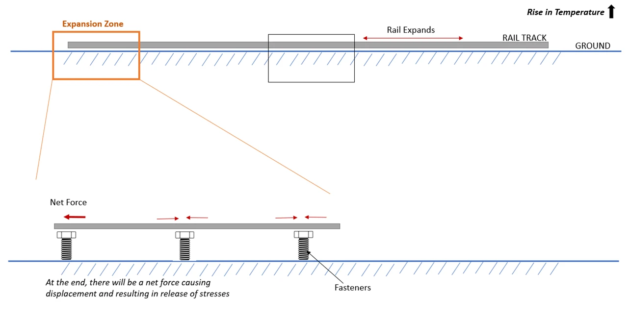
Figure 1.3 Effect of temperature change (Expansion zone)
Just by using the above concept, we can predict the stress profile for the CWR under the effect of temperature changes. This would look something like this as present in the UIC 774-3.
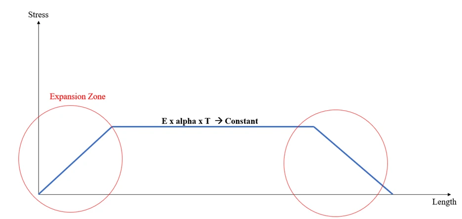
Figure 1.3 Effect of temperature change for CWR
C. Additional stress due to RSI
As per UIC 774-3,
- when an expansion device is not present the “changes in the uniform component of the temperature which cause a change in length in free moving structure” should be considered.
- and, the difference in temperature between the deck and rails, in the case of track with an expansion device.
Let’s take the same conditions as above and increase the temperature in the bridge deck and rail as shown in the below figure.
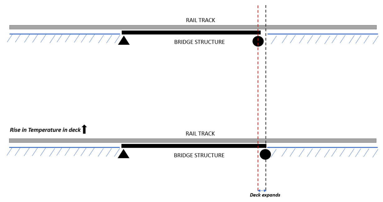
Figure 1.4 Deformation due to temperature change
In the rail section, thermal expansion and contraction are not permitted, as it is a continuously welded rail resting on an embankment which will not permit any movement of the rail section with temperature changes. In the rail section, additional stresses are developed due to the expansion and contraction of the bridge deck.
The stress that develops in a rail due to temperature changes is dependent on the boundary conditions of the bridge deck. As the temperature increase, the free end of the bridge deck expands, which in turn causes additional compressive stress to be exerted on the rail since the roller support is free to move. Similarly, at fixed support, the rail is not permitted to move, which causes additional tension stress in the rail.
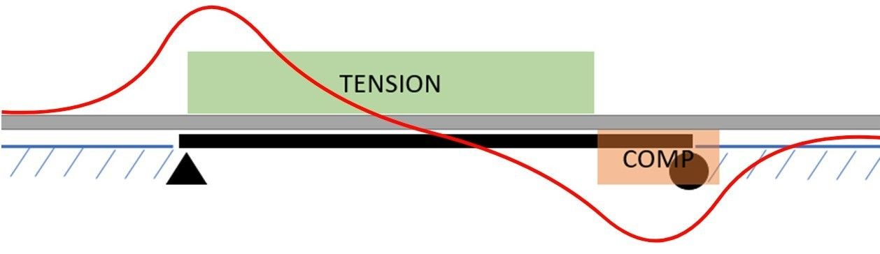
Figure 1.4 Axial stress for change in temperature (Simply supported condition)
Now instead of simply supported, let's say there are Elastomeric bearings at both ends. Now, both ends will experience compression and the middle of the rail will experience tension.
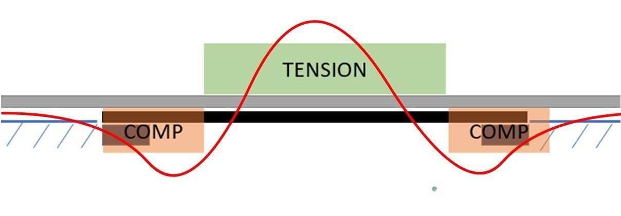
Figure 1.5 Axial stress for change in temperature (Elastomeric bearing)
1.2 Braking/ Acceleration
As the train moves, additional rail stress is also induced due to braking and traction. the vehicle will try to move the rail in the direction of movement, causing additional stress in the rail, these forces have the greatest impact on the region of the bridge support location. The maximum and minimum stresses are observed at the front and back ends of the train.
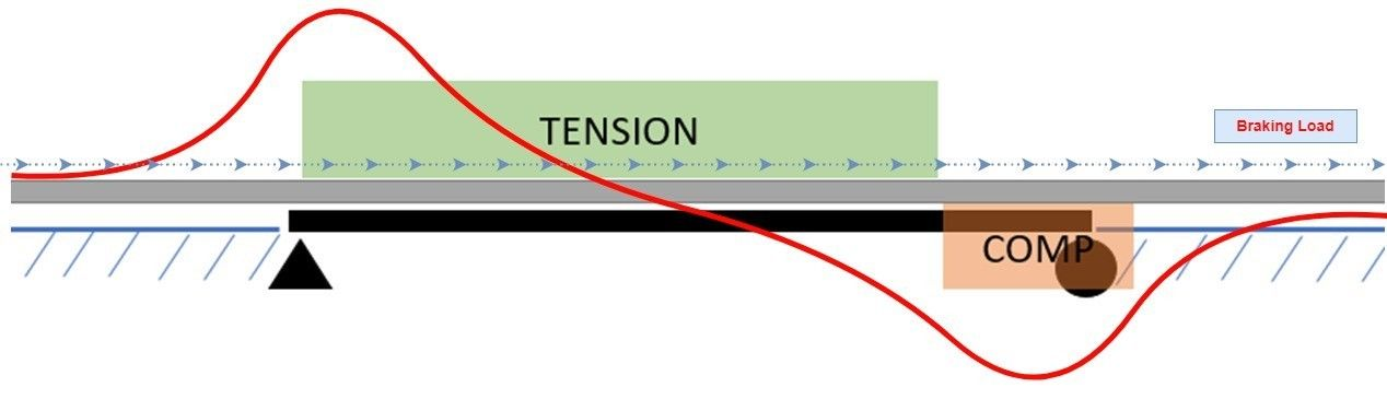
Figure 1.6 Axial stress diagram for braking load
1.3 Train Vertical Load
The additional stress is also generated in the rails when the train moves over the bridge due to the flexure of the deck. The rotation angle generated by bending at the support causes displacements of the rail as shown in the below image, which is also transmitted to the rails, generating additional stresses.
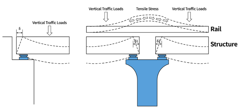
Figure 1.7 Displacement due to deck bending
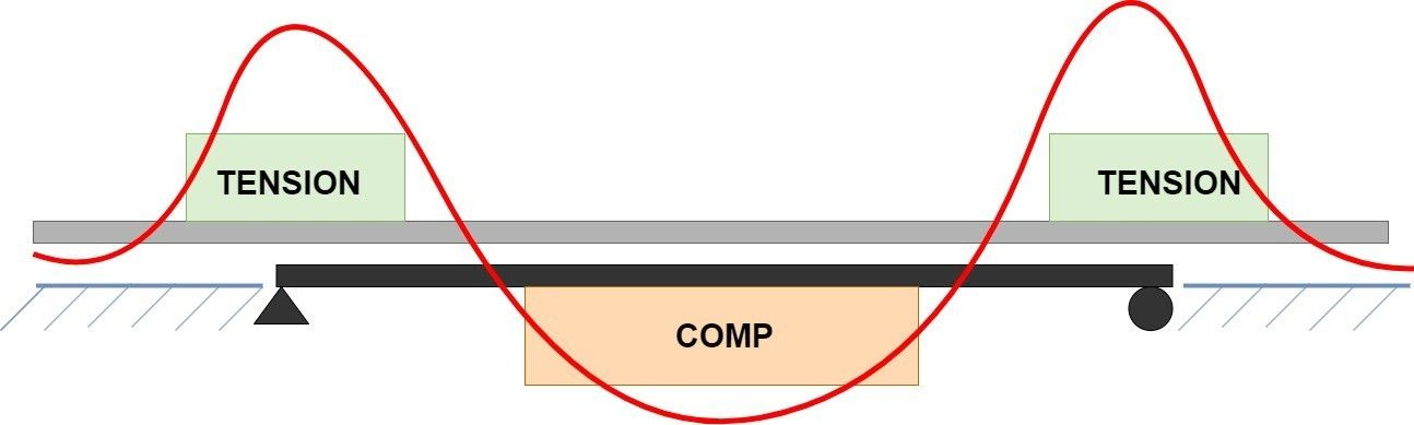
Figure 1.8 Axial stress diagram for train vertical load
📔 In order to accurately assess the impact of braking, acceleration, and vertical load for RSI assessment, it is necessary to consider multiple load cases by varying the position of the train to identify the most critical load case.

You can check more of these details in the download file.