 Get Started midas Civil
 Featured blog of this week

1. Introduction
With the recent development of high-speed trains globally, structural interaction plays an important role in estimating the impact of rail on the bridge and the optimum design of the bridge system for the safe passage of trains without disturbing the passengers' riding comfort. The UIC 774-3, Eurocode in 1991-2, RDSO, Korean code, ACI, and various codes and standards provide methodologies for considering rail-bridge interaction problems in the design and analysis of railway bridges. These guidelines take into account the dynamic interactions between trains and bridges, which can affect the stress, displacement, and stability of the rail during train passage. Based on experimental and numerical studies, these guidelines provide limiting values for stress, displacement, and stability of the rail to ensure railway bridges' safe and reliable performance. These limiting values are derived to prevent excessive deformations and stress in the rail that could lead to failure of the rail or other bridge components.
1.1 What is Rail-Structure Interaction
Rail Structure Interaction (RSI) is a complex phenomenon that occurs between the rail and the structure when Continuous Welded Rail (CWR) is used on a railway bridge. Unlike conventional rails, CWRs are continuous rails, so each displacement that occurs on bridges and rails is influenced by each other due to train loading (vertical and longitudinal direction) and temperature changes. Due to the following effects, safety problems such as buckling or fracture may occur on the rail during use. Therefore, when using CWR, it is necessary to review regardless of the type of train or track (ballast track, concrete slab track). Many parameters affect the rail-structure interaction. In most cases, the effects due to changes in temperature, acceleration/braking, and bending due to vertical loading play an important role.
1.1.1 Actions due to changes in temperature
The variation of temperature in long welded rail will cause expansion and contraction of
rail but the rail is connected to the sleeper using an elastic fastener which will prevent any
relative movement between the rail and the sleeper, which leads to the accumulation of axial force in the rail.
As per UIC 774-3, the following temperature load should be considered for the RSI.
- Rail = ± 50 °C
- Bridge = ± 35 °C
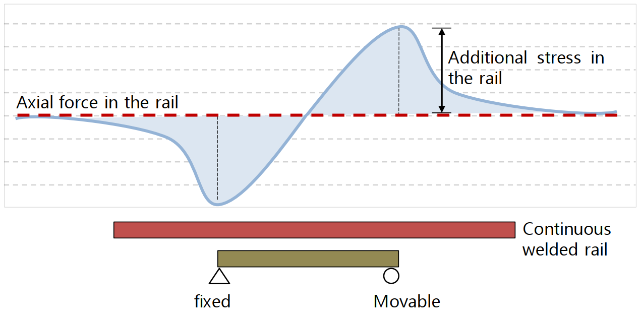
Figure 1.1 Axial force in the continuous welded rail
1.1.2 Actions due to braking and acceleration
As the vehicle travels along the rail depending upon the type of vehicle, longitudinal load, and direction of travel due to acceleration and braking of the vehicle it will try to move the rail in the direction of movement. Longitudinal resisting forces are generated by the longitudinal displacement of the rail due to braking and acceleration forces.
As per UIC 774-3, the following braking/acceleration load should be considered for the RSI.
- Acceleration: qlak= 33 kN/m per track, with L x qlak ≤ 1000 kN
- Braking: qlbk= 20 kN/m per track, with L x qlbk ≤ 6000 kN
 Figure 1.2 Braking and acceleration forces action on the bridge
1.1.3 Actions due to bending of deck
Vertical train loads cause bending of the superstructure and cause end rotation between the upper edge of the deck end or between the upper-end surface of the continuous deck as shown in the figure below.
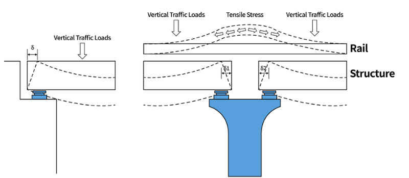
Figure 1.3 Displacement due to deck bending
In addition, due to the rotation angle generated by bending, displacements are also transmitted to the rails, generating additional stresses. The conceptual diagram of the horizontal displacements due to the bending of the superstructure is as follows.
 Figure 1.4 Effect of deck bending (UIC 774-3)
Vertical train loads should be loaded at the most unfavorable position to find the most critical effect.
1.2 RSI using a computer program
As per UIC 774-3 (1.7), Computer programs for track bridge interaction analyses should be validated before use for the test cases as specified in Appendix D. The software is considered to be validated when the error for the individual effect, as well as the overall effect, is less than 10%. However, UIC 774-3 also allows for a higher tolerance of 20% if the error is on the safer side.
Different levels of accuracy can be achieved by performing different types of analyses. As per UIC 774-3, the analysis can be categorized into the following 2 categories.
1.2.1 Simplified separate analysis model
Simplified separate analysis for thermal variation, braking/ acceleration forces, and vertical deflection. Which consists of creating two or more models for separate load cases. The results are combined assuming the principle of superposition, this is the simplest way of analyzing the Rail-structure interaction.
Case 1: Model with temperature loads, and resistance of ballast as per unloaded condition
Case 2: Model with vertical train load, acceleration, and/ or braking forces, which have different resistance of ballast (loaded/ unloaded condition) depending on the presence of train loads.
 Figure 1.5 Longitudinal resistance of the ballast for separate analysis
Since separate analysis is carried out for each load case, the assumption of zero initial stress and strain in the structure before train loading is considered.
When the thermal load is applied separately, initially the resistance of the ballast to the horizontal direction follows the “Unloaded Stiffness” curve up to the “Limit of resistance of unloaded track”. That is, it follows the “Unloaded Stiffness” curve until it reaches “Thermal Alone”. In addition to this, if the train load is applied separately, the horizontal resistance starts from the “Thermal Alone” point and follows the “Loaded Stiffness” curve until it reaches “Separate Train Load Added to Thermal”. The train load analysis uses “Loaded Stiffness”, but the final result is obtained by combining the train load analysis result with the thermal load analysis result. As a result, the ballast resists the extra load “Apparent increase in resistance of loaded track” besides the yield load under the “Loaded” state. Thus, the stress in the rail is overestimated.
1.2.2 Complete analysis model
Complete analysis for the simultaneous effect of the thermal variation, braking/ acceleration force, and vertical deflection. where the temperature load is applied first before the application of the vehicle load where the initial displacement due to temperature load is considered for the analysis when the moving load is applied.
 Figure 1.6 Longitudinal resistance of the ballast for a complete analysis
Before the train load is applied, the temperature affects the structure. The initial state of strain is taken into account during train loading. In other words, when the relative displacement of the rail to the bridge has already occurred due to the temperature load. If the train load is applied to a certain location, the behavior of the roadbed at which the train is located switches from the “Unloaded Bi-Linear Curve” to the “Loaded Bi-Linear Curve” and the displacements and the internal forces in the rail and the structure due to the temperature load are maintained.
If we compare the two types of analysis, it can be observed that the staged analysis results in lower compressive stress in the rail beneath the train, as it considers a larger yielding zone than the separate analysis. Therefore, the separate analysis overestimates the axial force because the resistance of the ballast at which train loading is applied is estimated to be the resistance under train loading plus the resistance under thermal loading, instead of the resistance under train loading alone.

You can check more of these details in the download file.


Download%20486_512.png)


